Wire Soldering: How to Avoid Those Infuriating Minor Mistakes?
This instruction manual will guide you from scratch to quickly master the entire wire soldering process and avoid those infuriating minor mistakes. Want to complete efficient and safe wire soldering operations easily? Keep reading. There's a wealth of practical information waiting for you!"
- Tools and Materials Used
- Tools:
- Electric soldering iron
- Hot air gun
- Diagonal pliers
- Long-nose pliers
- Phillips screwdriver
- Flathead screwdriver
- Blade
- Wire stripper
- Multimeter (used for inspection after soldering)
- Materials:
- Cable wire
- Solder
- Heat-shrink tubing
- 2KΩ, 1/4W color-coded resistors (used for series connection of the I/O lines of servo or stepper drivers)
Operation Steps
1、Preparation Work
- Verify the production instruction sheet and carefully check the cable model and required plug accessories concerning the electrical schematic diagram of the corresponding model.
- Check whether the tools and materials, including the electric soldering iron, hot air gun, solder, cable wire, etc., are complete.
- Please turn on the power of the electric soldering iron and adjust it to a suitable soldering temperature (about 350 °C is recommended).
- Turn on the exhaust fan to maintain air circulation and prevent inhalation of harmful gases.
2、Wire Soldering Operations
- Wire Cutting and Marking
- Cut the required length of cable wire according to the electrical auxiliary material extension line list of the corresponding model (refer to the specific specification requirements).
- Mark each type of cable wire with art paper tape and classify them for easy identification.
- Heat-shrink Tubing Installation
- Each cable wire must be fitted with a suitable heat-shrink tubing before soldering, and the heat-shrink tubing should be pushed to the end away from the soldering position to avoid being affected by high temperatures.
- Wire Stripping
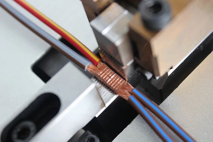
- The stripping length of the outer sheath of the cable wire is 10 - 20 mm, and the shielding layer should be twisted into a strand after stripping.
- The stripping length of each wire in the cable wire is 2 - 3 mm, ensuring that the wire core is neat and not messy.
- Pretreatment of Soldering Positions
- Before soldering, all soldering parts (including wires and plug pins) need to be pre-tinned.
- Before tinning, use tin wire to clean the tip of the electric soldering iron to prevent short circuits caused by solder residue.
- Soldering of Servo/Stepper Driver I/O Lines
- According to the electrical schematic diagram, connect the 2KΩ, 1/4W color-coded resistors in series to the designated control lines (pulse input lines, direction input lines) and solder them firmly.
- Formal Soldering
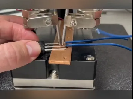
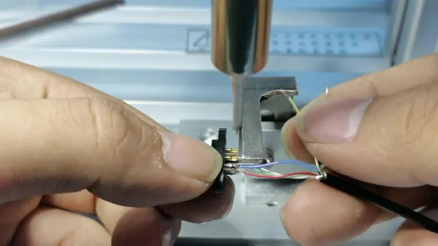
- When soldering, fix the plug, hold the wire in one hand and the electric soldering iron in the other hand.
- Place the wire on the correct plug pin and use the electric soldering iron to solder quickly. The size of the solder joint should be moderate to avoid short circuits or affecting the installation of heat-shrink tubing.
- Immediately install the heat-shrink tubing after soldering each wire to ensure that there is no short circuit between adjacent pins.
- Shielding Wire Treatment
- When the cable wire is a shielding wire, twist the shielding layer into a strand, cover it with heat-shrink tubing, and solder it to the grounding pin of the plug. After soldering, use a hot air gun to shrink the heat-shrink tubing to ensure good insulation of the shielding layer.
- Plug Assembly
- After all solder joints are completed and self-inspected without errors, use a hot air gun to heat the heat-shrink tubing to ensure that each solder joint is completely covered.
- When the plug has a housing, assemble the plug housing mark classify the wire materials according to their functions, and place them properly.
- Self-inspection
- After soldering is completed, use a multimeter to conduct a continuity test to ensure good conduction of the solder joints.
- Manually pull the wires slightly with force to ensure that there is no cold solder joint or false soldering phenomenon.

3、Precautions
4、Precautions During Soldering
Pay attention to the arrangement direction of the plug soldering pins to ensure that there is no wrong soldering.
The pins of the plug should not be short-circuited with each other. Even if a certain pin is not soldered, it is necessary to ensure that there is no solder residue.
The soldering speed should be fast and smooth to avoid damaging the plug or causing burns due to prolonged heating.
Unless otherwise specified, the pulse input lines and direction input lines of the I/O lines of servo or stepper drivers need to be connected in series with 2KΩ, 1/4W color-coded resistors.
5、Precautions for Heat-shrink Tubing Operation
Keep the distance between the heat-shrink tubing and the hot air gun at about 100 mm and adjust it appropriately according to the model of the hot air gun.
The heat-shrink time should not be too long to prevent the heat-shrink tubing from being damaged or the solder joints from becoming loose due to heat.
6、Safety of Electric Soldering Iron and Hot Air Gun
When the electric soldering iron is not used for a long time, apply a layer of solder to the tip of the soldering iron to protect it and turn off the power at the same time.
Pay attention to high temperature during operation to avoid burns.
7、Recording and Quality Control
When the color of the cable wire changes, it is necessary to record it in time and update the production documents.
Operators and quality controllers need to conduct quality control on the manufacturing process of each product to ensure that the product meets the factory standards.
Wire Soldering Inspection Standards
1. Missed Soldering
Refer to the electrical schematic diagram to ensure that all plug pins are soldered and all required 2KΩ, 1/4W color-coded resistors are soldered in place.
2. Wire Breakage
There should be no wire breakage or damage.
3. Cold Soldering, False Soldering
The solder joints should be firm and not loose. The wire should not fall off when pulled slightly with force.
4. Wrong Soldering
Ensure that soldering is carried out on the correct pins according to the requirements of the electrical schematic diagram and that the soldering sequence is correct.
5. Poor Insulation
The heat-shrink tubing should completely cover the solder joints without excessive heat shrinkage or being burned through.
The shielding wires should be soldered firmly, and the heat-shrink tubing should cover them completely without exposed parts.
The operation instruction manual focuses on detail clarity, operability, and safety to ensure that operators can correctly understand and execute it. If further optimization or adaptation to specific models is required, please adjust the content according to actual needs.


